Beamsplitter Ratios Explained: 50:50, 20:80, 40:60 and More
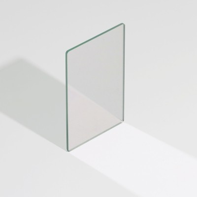
A beamsplitter ratio describes how an incoming beam is divided between the reflected and transmitted paths. A 50:50 splitter sends half the light each way; a 20:80 splitter sends 20% to one port and 80% to the other. The ratio is one of the first specifications to settle when you add a beamsplitter to a system.
Ratios are written as R:T, where R is the reflected fraction and T the transmitted fraction. The convention is not universal, so always check the datasheet: some suppliers quote transmission/reflection instead. For a 50:50 beamsplitter the ambiguity is harmless; for a 20:80 part it changes everything.
Why not always use 50:50? Because most applications do not want an equal split. In laser power monitoring, you may want only a small sample of the beam for a detector while the main beam continues almost untouched — a 90:10 or 95:5 splitter. In a microscope, a camera may need most of the light while a small fraction goes to a monitor port.
Common ratios include 50:50 for balanced paths and interferometers, 40:60 and 30:70 for mildly asymmetric division, and 20:80, 10:90 or 5:95 for sampling. Our beamsplitter range covers the standard values, and custom ratios are possible when your layout needs something specific.
Polarisation is the complication that surprises people. A standard plate splitter reflects s-polarised light more strongly than p-polarised light at 45°. If your source is polarised or your system is sensitive to it, the effective ratio may differ from the nominal value. A polarising beamsplitter is designed to separate polarisations entirely rather than split by intensity.
Wavelength also matters. A ratio is usually specified over a defined band, and it can drift outside that range. Broadband dielectric coatings hold the ratio relatively flat across the visible; specialised designs target a single laser line. Always check that the stated ratio covers your wavelengths.
Substrate and coating affect throughput and beam quality. A plate splitter introduces a small lateral displacement and, if the substrate is not compensated, chromatic differences between paths. Cube beamsplitters cement two prisms and largely avoid displacement, but use more material and add an adhesive interface to consider for high power.
Angle of incidence is fixed by design, typically 45°. Operating far from the design angle shifts both the ratio and, for polarising types, the extinction performance. Mount the splitter precisely and keep the beam centred on the coated area.
Surface quality and coating damage threshold matter in laser systems. For high-power beams, choose a splitter with a hard dielectric coating and a substrate such as fused silica; verify the LIDT at your wavelength and pulse conditions. A low-quality coating can be the weakest element in the whole path.
Tell us your wavelengths, polarisation state, desired ratio, power and beam diameter. We will recommend a standard beamsplitter or quote a custom-coated part with measured R/T data for your exact conditions.